|
COMPUTERS
|
|
SUPPORT
|
|
COMPARE
|
|
NEW
|
|
ABOUT US
|
|
WHERE TO BUY
|
|
SITE MAP
|
|
|
|
|
|
| PowerSpec PC Systems: Support Archives |
 |
Memory Installations
The following table shows several possible memory combinations.
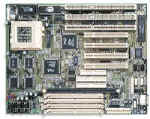
The P5VX-Be system board supports from 4-128MB. Memory can be installed
in a single DIMM or in pairs of 72-pin SIMMs. All 168-pin DIMM modules
must use unbuffered 3.3 volt RAM and supports up to a single 32MB
EDO or SDRAM. All EDO modules should be the same access speed, parity
/ non-parity, and configuration (single-sided, double sided, etc.)
within the banks.
|
Bank 0
|
Bank 1
|
DIMM
|
|
|
SIMM 1
|
SIMM 2
|
SIMM 3
|
SIMM 4
|
DIMM 1
|
Total system memory installed
|
|
-
|
-
|
-
|
-
|
8MB
|
8MB
|
|
-
|
-
|
- |
-
|
16MB
|
16MB
|
|
-
|
-
|
-
|
-
|
32MB
|
32MB
|
|
2MB
|
2MB
|
-
|
-
|
-
|
4MB
|
|
4MB
|
4MB
|
4MB
|
4MB
|
-
|
16MB
|
|
8MB
|
8MB
|
8MB
|
8MB
|
-
|
32MB
|
|
16MB
|
16MB
|
4MB
|
4MB
|
-
|
40MB
|
|
32MB
|
32MB
|
-
|
-
|
-
|
64MB
|
|
32MB
|
32MB
|
32MB
|
32MB
|
-
|
128MB (maximum supported)
|
|
CPU Frequency and Bus
Frequency Jumpers
|
Core Intel CPU Frequency
|
Host Clock
|
JP2
|
Clock Multiplier
|
JP11
|
JP12
|
|
75 MHz
|
50 MHz
|
1-2, 3-4, 5-6
|
1.5
|
1-2
|
1-2
|
|
90 MHz
|
60 MHz
|
3-4, 5-6
|
1.5
|
1-2
|
1-2
|
|
100 MHz
|
66 MHz
|
1-2, 5-6
|
1.5
|
1-2
|
1-2
|
|
120 MHz
|
60 MHz
|
3-4, 5-6
|
2
|
2-3
|
1-2
|
|
133 MHz
|
66 MHz
|
1-2, 5-6
|
2
|
2-3
|
1-2
|
|
150 MHz
|
60 MHz
|
3-4, 5-6
|
2.5
|
2-3
|
2-3
|
|
166 MHz
|
66 MHz
|
1-2, 5-6
|
2.5
|
2-3
|
2-3
|
|
200 MHz
|
66 MHz
|
1-2, 5-6
|
3
|
1-2
|
2-3
|
|
Cyrix 6x86
|
Core CPU Frequency
|
Host Clock
|
JP2
|
Clock Multiplier
|
JP11
|
JP12
|
|
P120+
|
100 MHz
|
50 MHz
|
1-2, 3-4, 5-6
|
2
|
2-3
|
1-2
|
|
P133+
|
110 MHz
|
55 MHz
|
1-2, 3-4
|
2
|
2-3
|
1-2
|
|
P150+
|
120 MHz
|
60 MHz
|
3-4, 5-6
|
2
|
2-3
|
1-2
|
|
P166+
|
133 MHz
|
66 MHz
|
1-2, 5-6
|
2
|
2-3
|
1-2
|
|
AMD K5
|
Core CPU Frequency
|
Host Clock
|
JP2
|
Clock Multiplier
|
JP11
|
JP12
|
|
PR75
|
75 MHz
|
50 MHz
|
1-2, 3-4, 5-6
|
1.5
|
1-2
|
1-2
|
|
PR90
|
90 MHz
|
60 MHz
|
3-4, 5-6
|
1.5
|
1-2
|
1-2
|
|
PR100
|
100 MHz
|
66 MHz
|
1-2, 5-6
|
1.5
|
1-2
|
1-2
|
|
PR120
|
90 MHz
|
60 MHz
|
3-4, 5-6
|
1.5
|
1-2
|
1-2
|
|
PR133
|
100 MHz
|
66 MHz
|
1-2, 5-6
|
1.5
|
1-2
|
1-2
|
CPU Voltage Jumpers
|
Single Voltage CPU type
|
JP6
|
CPU I/O Voltage
|
JP5
|
|
|
Includes
- Intel Pentium® processor
- Pentium® Overdrive® processor
- Cyrix 6x86
- IBM 6x86
- AMD K5 ABQ
|
2-3
|
3.3v
|
1-2
|
|
3.525v
|
3-4
|
|
Dual Voltage CPU type
|
JP6
|
CPU I/O voltage
|
JP5
|
CPU Core voltage
|
JP7
|
|
Dual Voltage (Power Split) CPUs include
- Intel Pentium® processor with MMX™ technology
- Cyrix 6x86L
- IBM6x86L
- AMD K5 AHQ..., etc.
|
1-2
|
3.3v
|
1-2
|
2.5v
|
1-2
|
|
3.525v
|
3-4
|
2.8v
|
3-4
|
|
2.9v
|
5-6
|
Other Jumpers
JP1 Password Check
- short = disable
- open = normal operation
JP4 Clear CMOS Setup
- short = clear CMOS Setup memory
- open = normal operation
Connector Table
|
Connector:
|
Function:
|
Description:
|
|
J1
|
PS/2 Keyboard (optional)
|
Connect to Mini-DIN PS/2 Keyboard (manufacturing option PS/2 keyboard
& mouse or AT keyboard connection)
|
|
J2
|
J2 AT Keyboard connector
|
Connect to DIN-5 AT Keyboard
|
|
J3
|
PS/2 Mouse (optional)
|
Connect to Mini-DIN PS/2 Mouse (manufacturing option PS/2 mouse
port w/ PS/2 keyboard port)
|
|
J4
|
Serial port #2
|
Connect to serial port #2 / bracket, can be configured COM2, COM4,
or disabled
|
|
J5
|
PS/2 mouse 5-pin header
|
Connect to PS/2 cable mouse / bracket
|
|
J6
|
Serial port #1
|
Connect to serial port #1 / bracket, can be configured COM1, COM3,
or disabled
|
|
J7
|
Dual port USB
|
Connect to 2 channel (connector) USB cable
|
|
J8
|
Parallel Port (LPT)
|
Connect to db-25 female parallel printer / bracket
|
|
J10
|
12-pin Power connector
|
Connect to power supply lead P8 and P9
|
|
J11
|
Floppy Drive Controller
|
34-Pin connector connects to 2-device cable; End device is A:,
middle device is B:
|
|
J12
|
Secondary IDE
|
40-pin connector connects to supplied 2-device cable; attach to
Secondary master / slave with supplied cable
|
|
J13
|
Primary IDE
|
40-pin connector connects to supplied 2-device cable; attach to
Primary master / slave with supplied cable
|
|
J14
|
Green LED
|
Connect to the Suspend LED. Blinking LED indicates low-power suspend
mode
|
|
J15
|
Hard Disk LED
|
Connect to the front panel Hard Disk activity LED
|
|
J16
|
Infrared (IR) connector for HP
|
Connects to Infra-Red cable / bracket
|
|
J17
|
Infrared (IR) connector for IBM
|
Connects to Infra-Red cable / bracket
|
|
J18
|
CPU Fan Connector
|
Connects to 2 or 3-pin CPU fan power connector
|
|
J20
|
Case features
|
Connections to front panel case features
- Pins 2-3: "Power ON" LED
- Pins 4-5: Suspend switch
- Pins 9-10: Reset Switch
- Pins 11-15: Keyboard Lock
- Pins 17-20: Speaker
|
|
| Call Tech Support.
For fee-based technical support, please call
1-614-850-3670 or send us
an email.
Remember, it's important to have your system, model, or serial number
ready when contacting our support staff with technical questions.
Need help? |
|