|
COMPUTERS
|
|
SUPPORT
|
|
COMPARE
|
|
NEW
|
|
ABOUT US
|
|
WHERE TO BUY
|
|
SITE MAP
|
|
|
|
|

| Call Tech Support.
For fee-based technical support, please call
1-800-207-3434 or send
us an email.
Remember, it's important to have your system, model, or serial number
ready when contacting our support staff with technical questions.
Need help? |
|
| PowerSpec PC Systems: Support System Boards |


|
|
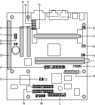
A
|
CD-ROM (ATAPI) (J2C2)
|
L
|
Diskette drive (J10F1)
|
|
B
|
Optional Line-In (J2C1)
|
M
|
Front panel (J10D1)
|
|
C
|
Telephony (J1C1)
|
N
|
Primary and secondary IDE (J9D1, J9D2)
|
|
D
|
CD-ROM (2 mm) (J2C3)
|
O
|
Optional PC/PCI (J8D2)
|
|
E
|
Optional fan 1 (J2J1)
|
P
|
Optional AMC (J7F1)
|
|
F
|
242-contact slot connector (J4F1)
|
Q
|
ISA slot (J4A2)
|
|
G
|
Fan 2 (J4J1)
|
R
|
Optional Wake on LAN technology (J4A1)
|
|
H
|
Fan 3 (J5J1)
|
S
|
Optional Wake on Ring (J3A2)
|
|
J
|
DIMMs (J6F1, J6F2)
|
T
|
Optional chassis intrusion (J3A1)
|
|
I
|
Optional TV Out (J6J1)
|
U
|
PCI slots (J4C1, J4B1)
|
|
K
|
Power supply (J7H1)
|
|
|
|
Power Supply Connector
When used with an ATX-compliant power supply that supports remote power
on/off, the motherboard can turn off the system power through software
control. See Section 6.2 for information about the ATX specification.
To enable soft-off control in software, advanced power management must
be enabled in the Setup program and in the operating system. When the
system BIOS receives the correct APM command from the operating system,
the BIOS turns off power to the computer. If power to the computer is
interrupted by a power outage or a disconnected power cord then power
resumes, the computer returns to the power state it was in before power
was interrupted (on or off). In addition, the motherboard supports the
use of small form factor SFX power supplies. An SFX power supply uses
the same connector as an ATX power supply, but does not provide -5 V to
the motherboard. For more information about the SFX specification, see
the Technical
Product Specification
Front Panel Connectors
|

|
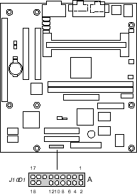
The front panel connectors includes connections for the following:
Reset Switch Connector
Pins 5 and 7 can be connected to a momentary SPST type switch
that is normally open. When the switch is closed, the motherboard
resets and runs the POST.
Power LED Connector
Pins 2 and 4 can be connected to a dual colored LED that will
light when the computer is powered on. The following table shows
the possible states for this LED.
|
LED State
|
Description
|
|
Off
|
Off
|
|
Steady Green
|
Running
|
|
Blinking Green
|
Running/message waiting
|
|
Steady Yellow
|
Sleeping
|
|
Blinking Yellow
|
Sleeping/message waiting
|
Hard Drive LED Connector
Pins 1 and 3 can be connected to an LED to provide a visual
indicator that data is being read from or written to a hard drive.
For the LED to function properly, an IDE drive must be connected
to the onboard hard drive controller.
Power Switch Connector
Pins 6 and 8 can be connected to a front panel power switch.
The switch must pull the SW_ON# pin to ground for at least 50 ms
to signal the power supply to switch on or off. (The time requirement
is due to internal debounce circuitry on the motherboard.) At least
two seconds must pass before the power supply will recognize another
on/off signal.
Infrared Module Connector
Pins 11 - 16 can be connected to an IrDA* module. After the
IrDA interface is configured, files can be transferred to or from
portable devices such as laptops, PDAs, and printers using application
software.
|
Rear Panel Connectors
|

|
|
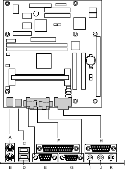
A,B
|
PS/2-keyboard and mouse connectors
|
|
C,D
|
Two USB connectors (stacked)
|
|
E
|
One serial port
|
|
F
|
One parallel port
|
|
G
|
Video
|
|
H
|
MIDI/game port
|
|
I,J,K
|
External audio jacks: Line Out (I), Line In (J), and Mic
In (K)
|
|
Jumper Locations and Definitions
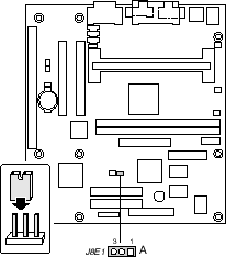
The motherboard has a single jumper block at location J8E1. The 3-pin
jumper block enables all motherboard configuration to be done in Setup.
The figure below shows the location of the configuration jumper block,
and the table describes the jumper settings for normal, configure and
recovery modes.
|

|
|
Function
|
Jumper J8E1
|
Configuration
|
|
Normal
|
1-2
|
The BIOS uses current configuration information and passwords
for booting.
|
|
Configure
|
2-3
|
After the POST runs, Setup runs automatically. The maintenance
menu is displayed (processor speed is set in this mode).
|
|
Recovery
|
none
|
The BIOS attempts to recover the BIOS from a floppy disk.
A recovery diskette is required.
|
Caution: Do not move the jumper
with the power on. Always turn off the power and unplug the power
cord from the computer before changing the jumper.
|
Processors Supported
Different versions of the MU440EX motherboard provide different
processor support. A small barcoded label, similar to the diagram shown
below, can be found on the component side of the motherboard. The numbers
following the letters "PBA" or "AA" can help identify the version of your
motherboard.


Also, note whether your BIOS version is 4M4UE0X1 or 4M4UE0X3. After locating
the PBA or AA number and BIOS version, consult the tables below to determine
which processors are supported by that motherboard.
Supports only Intel® Celeron™ processors 266, 300, 300A, 333, 366, and
400 MHz:
|
AA Number
|
PBA Number
|
BIOS Version
|
|
698722-402
|
695747-402
|
4M4UE0X1
|
|
702993-402
|
695747-402
|
4M4UE0X1
|
|
702999-402
|
695747-402
|
4M4UE0X1
|
|
698722-403
|
695747-403
|
4M4UE0X1
|
|
702993-403
|
695747-403
|
4M4UE0X1
|
|
702999-403
|
695747-403
|
4M4UE0X1
|
|
698722-404
|
695747-404
|
4M4UE0X1
|
|
702993-404
|
695747-404
|
4M4UE0X1
|
|
702999-404
|
695747-404
|
4M4UE0X1
|
Supports both Pentium® II processors with 66 MHz Front Side Bus and
Intel® Celeron processors 266, 300, 300A, 333, 366 and 400 MHz:
Note 1: In the table below, support is available beginning at the
-xxx level shown and any subsequent -xxx revisions.
Note 2: Support for Intel® Celeron™ processors 300A, 333, 366 or 400
MHz requires either BIOS 4M4UE0X1.86A.0011.P10 or later or BIOS 4M4UE0X3.86A.0004.P03
or later--depending on which version (4M4UE0X1 or 4M4UE0X3) matches your
board.
|
AA Number
(see note 1)
|
PBA Number
(see note 1)
|
BIOS Version
|
|
698722-405
|
695747-405
|
4M4UE0X1
|
|
702993-405
|
695747-405
|
4M4UE0X1
|
|
702999-405
|
695747-405
|
4M4UE0X1
|
|
718611-404
|
713826-404
|
4M4UE0X1
|
|
716192-404
|
716190-404
|
4M4UE0X1
|
|
718619-405
|
718658-405
|
4M4UE0X3
|
|
718631-405
|
718658-405
|
4M4UE0X3
|
|
718659-405
|
718658-405
|
4M4UE0X3
|
Warning: Processors not specifically listed by type and rated
speed may have requirements that are not supported by the motherboard's
design. Use of unsupported processors may result in improper operation,
damage to the motherboard or processor or reduced product life.
Intel® MU440EX Motherboard
Technical Notes:
Installing the Retention Mechanism
There are at least two types of fasteners used to attach the retention
mechanisms to the motherboard:
1. Retention mechanisms with captive brass fasteners
To install retention mechanisms with captive brass fasteners, simply use
a Number 2 Phillips screwdriver to screw the fasteners on the pre-installed
brass Pemstuds.
2. Retention mechanisms with plastic fasteners
To install the retention mechanisms with plastic fasteners:
- Leave space below each mounting hole for the fastener to protrude
through the hole.
- Find the slot 1 connector on the motherboard.
- Position the retention mechanism on the motherboard next to the slot
1 connector.
- Push down on the retention bracket until the black plastic fasteners
are correctly seated and the retention mechanism fits snugly against
the board.
Critical Step - Push each white retainer pin into its respective
black fastener until the head of each pin is seated onto the head of each
fastener.
When installing the retention mechanism, make sure the motherboard is
supported so that it will not bend while the retention mechanism is being
pressed into the mounting holes. Do not place the motherboard on
a hard surface to install the retention mechanism. Placing the motherboard
on a hard flat surface can push the retention mechanism posts upwards
so that the retainer pins are unable to fully secure the mechanism. This
can cause the retention mechanism to become loose allow the processor
could fall out. Instead to install the retention mechanism with the motherboard
on anti-static foam (for example, the foam used to boxed Intel® motherboards
for shipping).
CD-ROM or Second IDE Hard Drive Issues:
There are two known issues involving CD-ROM or secondary hard drives:
- The retail version of Microsoft Windows® 95 may not recognize the
Intel® 82371EB PIIX4e IDE controller used on Intel motherboards, causing
the secondary IDE channel to be disabled. This can result in IDE devices
(such as CD-ROM drives) not being detected or disappearing after the
system is rebooted. A utility is available to update the MSHDC.INF file
and resolve the issue.
- Windows® 95 also may fail to recognize a CD-ROM drive that does not
comply with the ATAPI specification. A technical advisory covers this
issue for Intel motherboards using the 82371EB PIIX4e IDE controller.
|


